

ROTAX 2-STROKE FUEL SYSTEM DESIGN:
The majority of engine failures are caused by fuel system faults or contamination in your fuel system. Many problems can be prevented by regularly checking the operations of the fuel system, and using the correct components or parts.
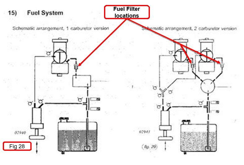
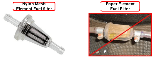
A lot of people are using paper fuel filters in their fuel systems and there are some major issues in doing so. The paper element can absorb water and at altitude this water can freeze, starving the engine from fuel. A suitable fuel filter of 0.15 mm mesh size should be used and must be fitted between the fuel pump and carburetor (See figure 28).
Below is an example of a type of fuel filters that is recommended - versus a type which is not recommended.
Other issues that are commonly found are either improperly routed fuel lines or improperly secured fuel lines.
Air leaks in the fuel system can considerably reduce the capacity of the fuel pump and cause a vapor lock. The fuel line between the tank and fuel pump is under considerable negative pressure when the engine is running hard, and the tiniest flaw in any joint will cause air to be sucked into the system. Air leaks are much more dangerous when the fuel tank is mounted below the fuel pump and carburetor.
Zap straps/Tie wraps should not be used to secure the fuel line to a joint and some commercial clamps are often not very satisfactory on small pipes as they tend to tighten up oval creating a possible leak. “Crimp on” clamps can be unsatisfactory if incorrectly applied and are difficult to remove for servicing.
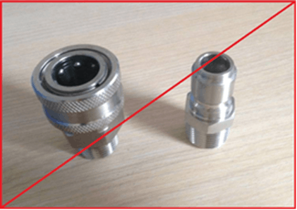
Quick release type connectors can cause air leaks, and also produce flow restrictions and possible blockage sites.
Replace all doubtful fuel line clamps with good quality approved ones. Rotax recommends a spring type clamp P/N 938 195. This type of clamp has been proven and is the most recommended.
Air leaks are obviously impossible to see, but the following checks will show if they exist:
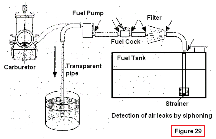
Referring to Figure 29 above, disconnect the fuel line from the carburetor and connect a length of transparent fuel pipe, making sure the connection is absolutely airtight. Take the transparent pipe down to ground level and start siphoning fuel from the tank to a container on the ground. All parts of the fuel system above the level in the tank will be below atmospheric pressure, and any air leaks in the system will show up as bubbles in the transparent pipe. Continue siphoning for a considerable period of time.
After an initial settling period there should be no bubbles in the fuel. If bubbles persist, find the location of the air leaks(s) by process of elimination.
Another way of checking for air leaks is to replace the last portion of fuel line before the carburetor with a transparent piece. Ground run the engine and look for bubbles in the line – there should be virtually none after a few minutes settling down.
NOTE: Filter and fuel tap are shown on suction side of pump to illustrate air leakage sites possible. But it is recommended that these be installed on the pressure side of the pump.
ELIMINATION OF AIR LEAKS
If air leaks are indicated, seek to eliminate them. The arrow on the diagram show possible air leakage points. All connections on the suction side of the fuel pump are potential air leakage sites; the less there are, the less problems are likely to arise. It is far more satisfactory if the fuel tap and filter are fitted between the fuel pump and the carburetor, on the pressure side. On installations where this is not the case, extra care must be taken to eliminate air leaks.
A useful way of checking the fuel system between tank and carburetor is to fit a pressure gauge in the fuel line just before the carburetor. At full throttle the pressure should be 0.2-0.5 Bar (2.9 to 7.2 psi). A pressure gauge and fitting kit is now available from Rotax and may be permanently fitted to the aircraft or used as a fault finding tool.
A pressure lower than 0.2 bar indicates a serious problem. We rarely find a faulty pump, so always look elsewhere first.
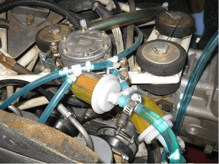
Below is an example of a bad fuel system installation on an aircraft that was involved in an accident. (See if you can spot the potential air leaks)
Accident Report Example
Below is an NTSB accident report that identifies a loss of engine power due to air being introduced into the fuel system.
|
NTSB Identification: CEN10CA160
Aircraft: ULTRALIGHT AMERICA SPITFIRE II MODEL CTV, registration: N6524R
The non-certificated pilot was conducting visual patterns in the experimental aircraft. While in the pattern, the airplane's engine began to sputter and lost partial power. The pilot examined the clear fuel lines and saw air bubbles. The pilot attempted to prime the engine to clear the air bubbles, but was not successful. The pilot then steered the aircraft toward the runway in an attempt to land quickly, but could not maintain level flight, so the pilot began a descending turn for the runway. Once the pilot realized that he would not make the landing surface due to strong winds, he elected to perform a forced landing to an open field. While maneuvering to land, a gust of wind increased the angle of bank and the pilot lost control of the airplane. The airplane impacted terrain nose-low, with approximately 45 degrees of bank. Substantial damage was sustained to the outboard portion of the left wing. The airplane was flown by the pilot and the previous owner prior to the accident without any problems. An examination of the fuel system and fuel lines did not reveal the source of air in the fuel lines.
The National Transportation Safety Board determines the probable cause(s) of this accident as follows: The pilot's failure to maintain control while maneuvering during a forced landing after a partial loss of engine power. |