Gregor, I would like to help you, but I'm going to have to ask some questions first to understand the problem.
1. Do you have a wiring diagram for this aircraft that you can post here?
2. Is the battery master switch turned on (closed) when this problem happens?
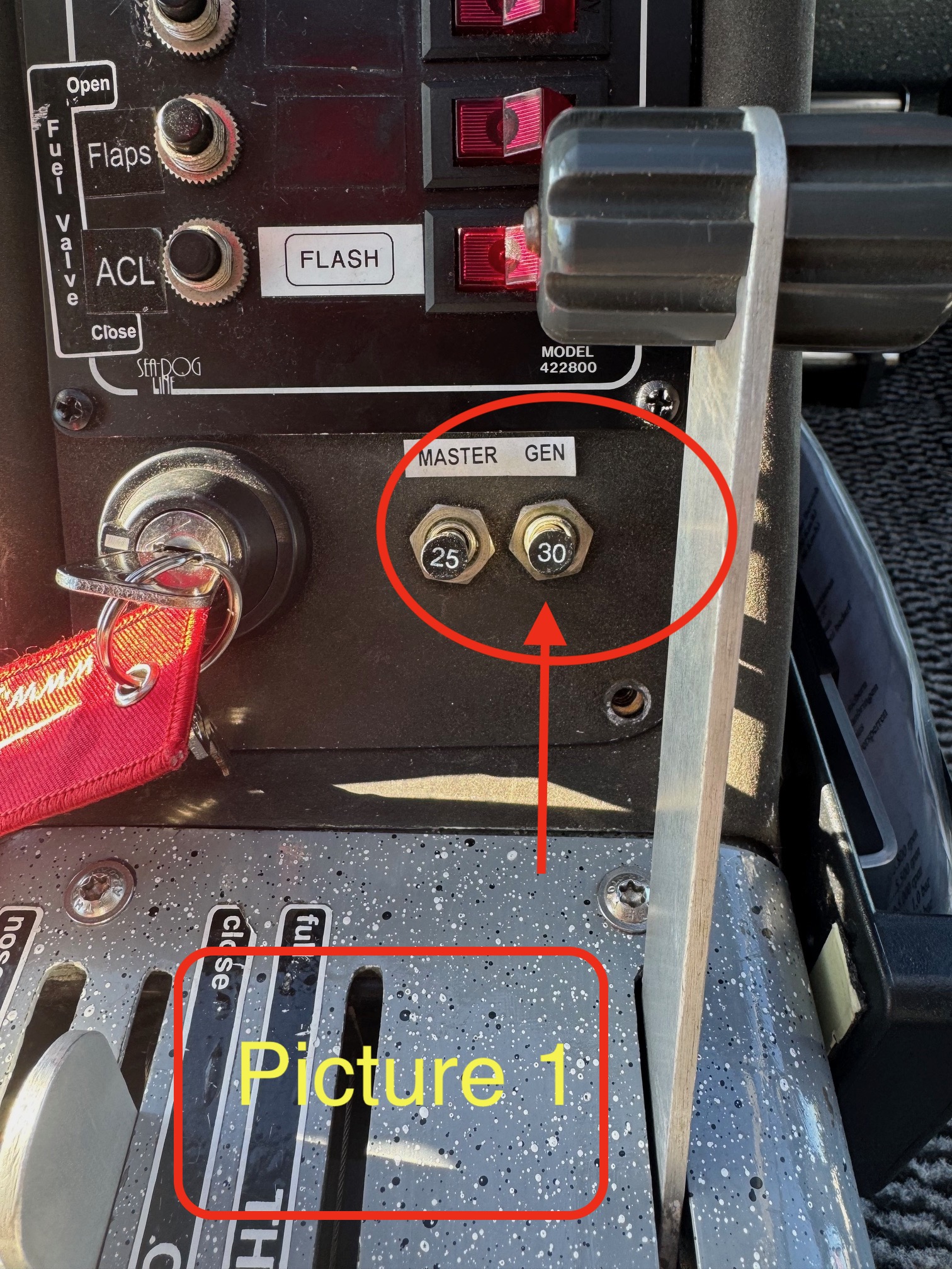
3. In Picture 1, the device that you circled is a 30A circuit breaker, not a switch. Does the problem occur any time this circuit breaker is closed, or is there a switch somewhere else?
4. You said that a fuse blows. Are you talking about the 30A circuit breaker in Picture 1, or is there a fuse somewhere else? If it is the 30A circuit breaker, does it pop out as soon as you push it in?
5. You said, "...power goes directly to the starter." Do you mean that the starter starts to turn the engine?
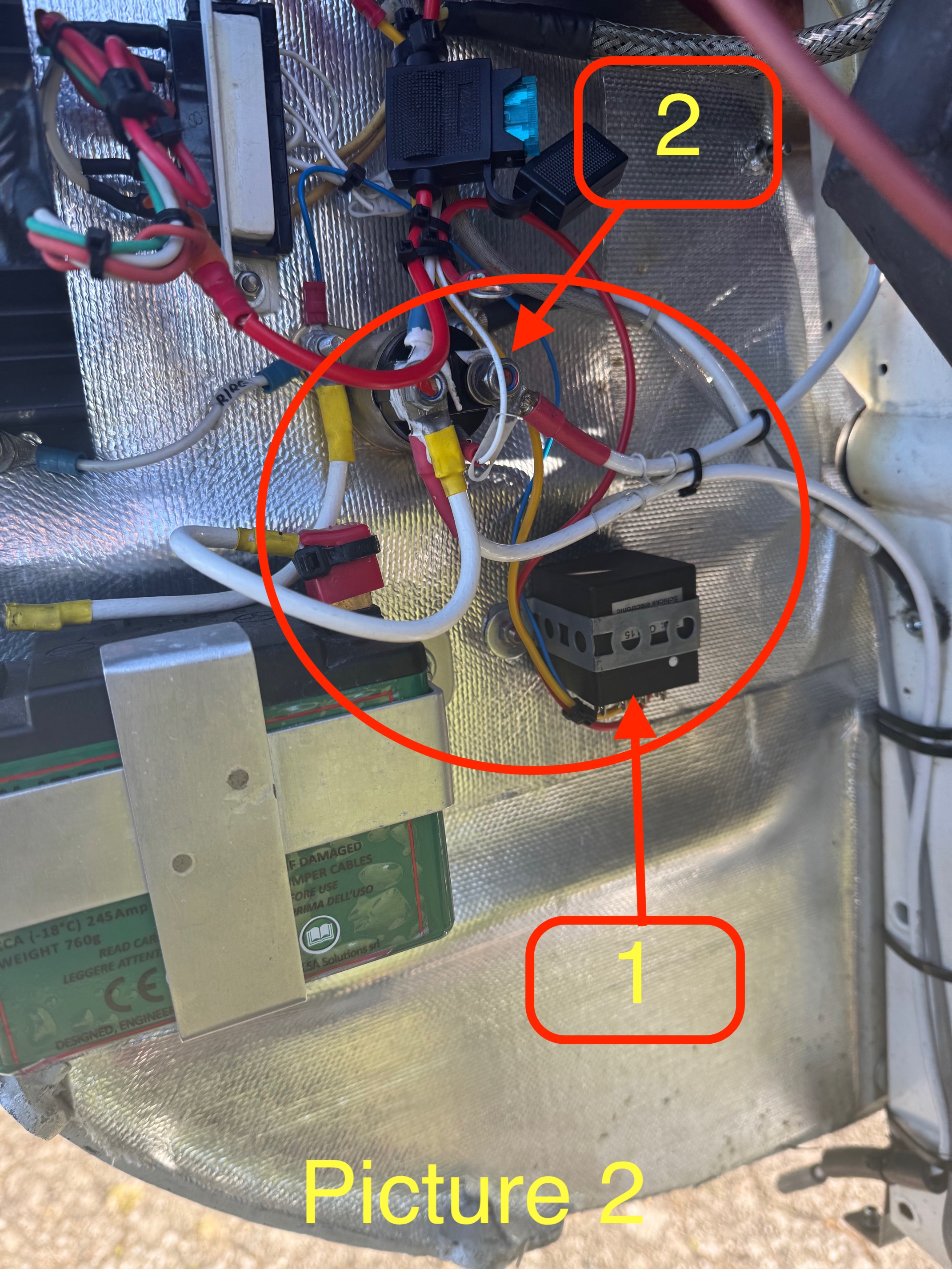
6. In Picture 2, it appears that you have disconnected the red wire coming from the OVP 15.2 (the battery positive wire) from a contactor on the firewall. This is the battery contactor, correct?
For anyone else who wants to help, here is the wiring diagram for the Schicke OVP 15.2 unit. It appears to be a relay with some control electronics that senses high voltage at the battery (>15.2V?) and opens the relay to stop charging. So, overvoltage protection for the battery only. Interesting device... perhaps intended to prevent the BMS from disconnecting the battery from the bus by never letting it see an overvoltage condition?

The unit marked "GR6" is a Schicke Electronics voltage regulator.
"gelb" = yellow / "blau" = blue / "rot" = red / "hauptschalter" = main switch / "starterrelais" = starter relay / "generatorsicherung" = generator fuse