It’s good to report, that in the five years since their introduction, their performance and reliability has been much better than the predecessor 2nd generation fuel pumps P/Ns (part numbers 892542 and 892546).
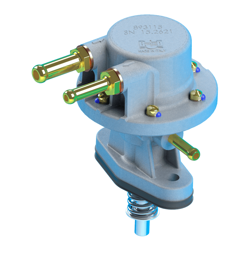
These pumps can be readily identified at a glance by the distinctive “AC” stamped into the top of the fuel pump. (Figure: 2)
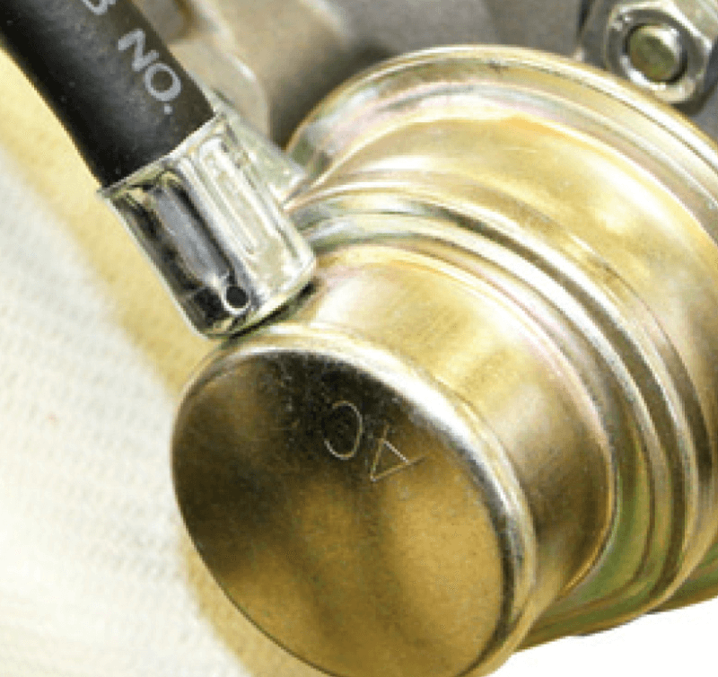
(Figure 2: Second Generation Fuel Pump)
But more specifically by the part number engraved onto the base of the fuel pump mounting flange. (Figure: 3)
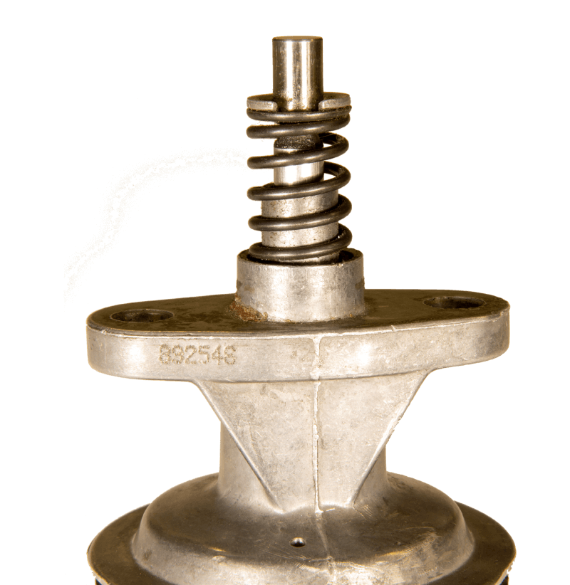
(Figure 3: Part Number Identification)
If you’re wondering about the difference between the two part numbers, it’s simply the same fuel pump, one with hoses pre-installed and the other without.
Accurately and completely generating a 3D model allows us to showcase the internal workings of the fuel pump with cutaways, transparencies, drawings, exploded views, and renderings that are unsurpassed in conveying concepts in the classroom. The only way to get a truly accurate 3D model of the fuel pump is to disassemble a pump for reverse engineering. This is a completely destructive process requiring cutting into many of the components to obtain accurate dimensions, especially on enclosed parts.
It’s hard to get excited about cutting into a brand-new $200 fuel pump, destroying its usefulness, simply for the privilege of measuring each component. However, fortune smiled upon us, when our request for a damaged fuel pump was fulfilled by one of our former students. And although the 3D model and associated renderings for this article are primarily about the new fuel pump, it is always fun to showcase the capabilities of Solidworks 3D modeling software which is available free to EAA members.
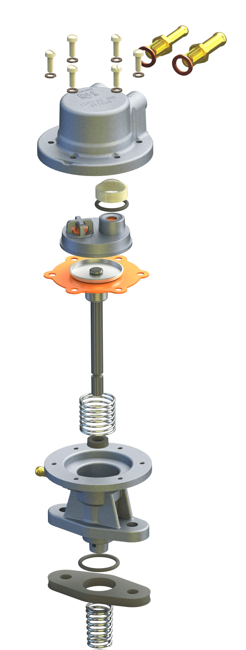
(Figure 4: Exploded View)
Now that we can “see” inside of the fuel pump, we can get a better understanding of how it works. Overall, the basic operation is similar to that of almost all mechanical fuel pumps being manufactured. The conceptual technology of a diaphragm and two check valves to move a fluid has been around for hundreds of years. When it comes to aircraft, the trick is, making it reasonably priced, lightweight, and most importantly, safe and reliable. The challenge here, is obvious considering we are now working on generation three of fuel pumps for the Rotax 912. (Figure: 4) above shows the internal components that make up the fuel pump. The base of the fuel pump is attached onto the gearbox housing and the pump shaft is actuated by an eccentric cam attached concentrically to the propeller shaft. A heavy spring, (with a force of approximately 50 pounds per inch travel) is located at the base of the fuel pump housing and is attached to the fuel pump shaft with a “cup” washer and retaining clip. This essentially holds the pump shaft against the eccentric cam on the prop shaft. This is where we find some of the greatest misconceptions regarding the operation of the fuel pump. The other end of the pump shaft is not directly connected to the diaphragm, but rather, free floats inside of a “bell housing” which is directly connect-ed to the diaphragm. (Figure: 5)
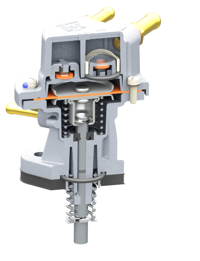
(Figure 5: Cutaway View)
The shaft makes contact with the lower portion of the bell housing and can pull down on the diaphragm, but “free” floats into the bell housing as the shaft is actuated into the pump by the eccentric cam on the prop shaft. Since it is not possible for the cam to pull on the pump shaft, it is the spring pressure alone that creates the force to pull down on the diaphragm. And since there is no connection from the pump shaft to the diaphragm on the upstroke, it is the internal spring, and only the pressure from that spring that can cause the diaphragm to move in the upward direction. This internal spring (with a force of approximately 22 pounds per inch travel) is by default what controls the pressure on the fuel pump. Surface area of the diaphragm divided by spring force equals fuel pressure. The only movement of the diaphragm, is, a result of the fuel moving through the fuel pump. On engines at idle and without a fuel bypass back to the fuel tank, the amount of diaphragm movement is minuscule. And at full throttle with a built-in fuel bypass the amount of diaphragm movement is going to be much more significant. The pump shaft on the other hand, has the identical amount of travel for each revolution, irrespective of diaphragm movement. It is the combination of the two springs that cause the diaphragm to move. The heavier external spring pulls down on the diaphragm essentially priming the pump. In the internal lighter weight spring pushes up on the diaphragm causing fuel pressure and flow.
We have recently talked to a mechanic that had modified dozens of fuel pumps by cutting down the length of the external spring thinking that this would reduce fuel pressure. Although you “can” reduce the fuel pressure this way, he had missed the bigger picture. For this premise to work, the external spring would essentially not be priming the pump as much. The pump shaft would be floating and bouncing on and off of the eccentric cam on the prop shaft creating the potential for premature failure. Additionally, this would be, essentially, reducing the total capacity of the fuel pump. We often say in class that “when you find yourself modifying a component you are essentially claiming that you are smarter than all of the collective knowledge of the engineers at the Rotax factory”. In this particular case, the mechanic was trying to solve a symptom of a bigger problem. He was attempting to remedy a needle and seat leaking problem that he, ironically, had created by another misunderstanding of the basic physics involved in that system.
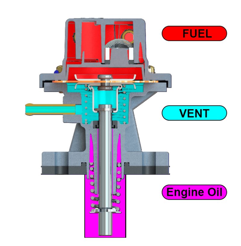
The pump shaft is lubricated by two slots cut into the lower housing that run either side of the length of the bearing surface for the pump shaft. A “Garlock” type seal prevents oil from leaking into the center of the pump. This is one of the areas where the 2nd generation “AC” pumps suffered problems. For the diaphragm to move, the underside needs to be vented to atmospheric pressure. Gen 2 pumps have two small vent holes on either side of the lower pump housing. It was not uncommon for the Garlock seal to start leaking. And although the leaks were typically very small, having that oil blown around the inside of the cowling and typically onto the windshield and fuselage was rather disconcerting on an engine that otherwise would normally make it to TBO without a single leak. On the new style 3rd generation fuel pumps a drain nipple is incorporated into that center portion of the fuel pump that separates the fuel pumping section from the oil lubrication and actuation section. (Figure: 6) A line can now be directed from the fuel pump down past the exhaust system and out the belly of the aircraft. Oil coming out of this line indicates a Garlock seal failure.
Fuel coming out of this line indicates a fuel diaphragm failure. As you might imagine, having fuel or oil for that matter dumping directly into the engine compartment isn’t ideal. However, the purpose of this vent hole was twofold. It supplied additional information about the condition of both the Garlock seal and the pumping diaphragm. Many builders are now incorporating a small (vented) collecting bottle at the end of this vent line to capture any leakage for inspection and evaluation purposes. Theoretically, locating the vent line in a higher or lower pressure area would act as an additional force on the pumping spring changing fuel pressure. The dual check valve subassembly is very traditional. Consisting of two fabric reinforced silicone pads that act as check valves backed up by very small springs. These allow flow of fuel in one direction only. And the springs are lightweight enough to easily allow flow of fuel from an electric boost pump to flow freely through the pump. The inlet and outlet side of the pump can be identified by the arrows embossed on the top of the fitting bosses. In addition, the inlet fitting is larger diameter than the outlet fitting. As the diaphragm is pulled down by the lower external spring, the fuel is drawn in through the inlet fitting and into the inlet chamber where there is a flexible plastic filter (approximately 400 micron) that protects the check valves against contamination. Even a small piece of contaminant can get under the face of the check valve disabling its function, and as a result, it is a critical component in the fuel pumps operation. Gen 2 pumps also contain an internal filter, but it is located where it is impossible to inspect or clean.
Let’s be clear, all three generations of fuel pumps are considered non-repairable. Even the new generation pumps have screws around the perimeter which will allow you access to the diaphragm and the pump shaft seal, but they are still considered non-repairable. Each of the screws has “torque seal” applied at the factory. Disturbing the torque seal by removing the screws voids the warranty on the pump. In reality, there isn’t any reason to be opening the pump in the first place. The primary function of the pump is the check valves, and these components are pressed into the check valves housing subassembly. Even the housing that holds the check valves in place is pressed into the top of the fuel pump. It required that we drill a hole through the top of the fuel pump and use a punch to extract the check valve subassembly for 3D modeling. This is the component that would have to be removed to have access to the plastic fuel filter. However, unlike the generation 2 pumps, you can get visual access to the fuel filter by removing the inlet nipple. (Figure: 7)
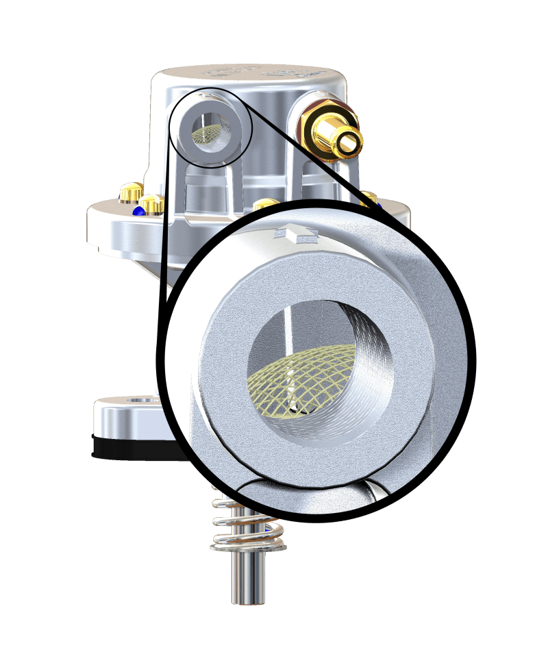
(Figure: 7 Filter Inspection)
Although, it would still be challenging to clean any contamination from the inlet chamber, having access for troubleshooting purposes is invaluable. Keep in mind that the plastic screen is delicate and fragile. You would never want to use shop air to try and blow through the fuel pump. Blowing backwards through the pump is impossible because of the check valves. And blowing in the normal direction of flow would most certainly damage the plastic filter. Keep in mind, the primary method used in keeping contamination from getting to the fuel pump in the first place is the aircraft or engine fuel filter. Finding contamination in the float bowls of the carburetor, by default, would mean that contamination had to also have also passed through the fuel pump filter.
The overall design of this new fuel pump meets all the criteria that we talked about in the introduction, Low cost, light-weight, safe, and reliable. The expectations are that the number of fuel pump related engine problems will be significantly reduced. There will likely continue to be problems created by the operators, but we may have even curbed that problem a bit now that we have undertaken the task of 3D modeling the fuel pump showing the inner workings. Perhaps it will quell that inevitable urge that permeates all aircraft builders: that curiosity to take things apart and see what’s going on inside.
| This article prepared by |  |
